Aerodynamicists are always looking for the best aerodynamic shape when designing something new. However, what makes a shape the best one? For example, when designing a new aircraft, what’s make a specific wing planform the best possible? Unfortunately, there is no simple answer to this simple question.
Many factors, such as aerodynamic performance, aircraft weight and so on, must be taken into account. If the design process is carried out by human designers, they change the parameters, such as wingspan or chord distribution, until they are happy with the aircraft performance. The design can then move to the next level.
Optimisation: looking for the best trade-off
The process can be seen as an optimisation [more]. The factors to improve are seen as objectives to minimise or maximise. Their values depend on the parameters which define the problem. Thus, a given set of parameters correspond to a specific geometry which, in turn, provides specific values of the objectives. Ideally, this is a way to decide which geometry is better. The optimisation can be performed automatically using a computer. An algorithm, which can belong to the family of gradient-free [more] or gradient-based [more] methods, provides the new sets of parameters which must be assessed in order to identify the best ones.
However, the automatic optimisation process won’t replace the human designers. It should be seen as an enhancing tool which helps to detect better solutions using less time instead.
What about an example?
Let’s have a look at an example now. The Common Research Model [more] is a research case which resembles a large civil aircraft. This kind of aircraft usually fly in transonic flow [more] when they are at cruise condition. For this reason, their wing planforms show some specific features such as backward sweep angle [more] and tapering [more]. Optimisation can be applied to the wing planform only in order to improve the overall aircraft performance. Let’s summarise the steps to take here:
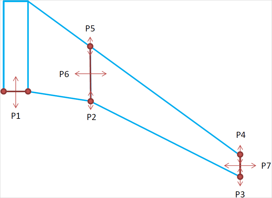
1 – Parametrisation of the wing planform
The aircraft wing is parametrised, i.e. any possible geometry is described using a set of 7 parameters. The smallest number of parameters, which is able to describe the problem, should be chosen.
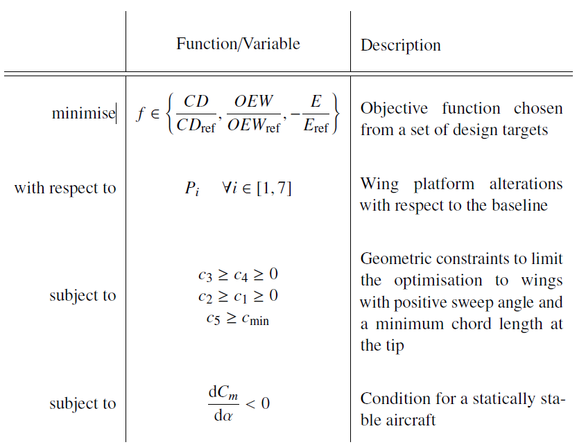
2 – Formulation of the problem
Three objectives are identified: drag coefficient [more], aerodynamic efficiency [more] and operating empty weight [more]. These are strongly correlated to the Breguet equation for the aircraft range [more]. Improving these objectives leads to a modified aircraft which can go further or faster than the baseline using the same amount of fuel.
$$
R \propto \frac{C_L}{C_D} \frac{OEW + Payload}{OEW}
$$
where \(\frac{C_L}{C_D}\) is the aerodynamic efficiency and \(\frac{OEW + Payload}{OEW}\) is the ratio between the total weight and the operating empty one.
Besides objectives, a number of constraints must be taken into account too. These limit the possible wing planforms by excluding some unpractical ones. For example, a stable aircraft is desirable [more] or a minimum length for the chord distribution is needed. All planforms which do not meet the requirements are excluded.
3 – Choice of the algorithm
The optimisation algorithm will be in charge of generating new geometries and assessing them. Thus, an efficient algorithm and an efficient implementation can improve the quality of results and the total time needed to perform the optimisation. A very simple algorithm is the Particle Swarm Optimisation [more] which belongs to the family of evolutionary algorithms.
4 – Results!
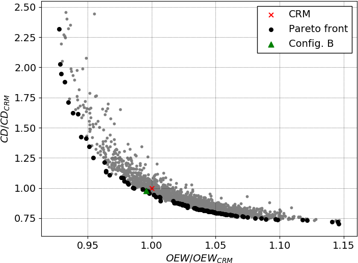
When more than one objective is taken into account there is no unique optimal wing planform. Conversely, a set of optimal geometries can be identified and they all lay on the Pareto front [more]. For example, when two objectives are considered, the Pareto front is curve in the 2D parameter space and its approximation is a set of 2D points along such curve. This is what happens when both drag coefficient and operating empty weight are minimised:
What about 3 objectives then? The Pareto front is now a surface!
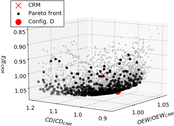
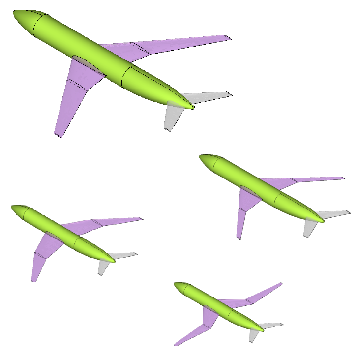
and the mathematical formulation of the Pareto front holds for 4+ dimensions, of course. Every point on the Pareto front corresponds to a new wing plaform and each of them is an optimal configuration.
More details?
All the pictures were taken from doi.org/10.1155/2019/4327481. More information can be found in the main article (freely available) at doi.org/10.1155/2019/4327481. Please, feel free to contact me.
Leave a Reply